Friday 31 January 2014

Noteworthy things #2

It is not on Thingiverse, and it is not specifically designed to be 3D printed, but it is super cool! A detailed 3D model (actually multiple models) of the Eagle transporters from the TV show Space: 1999 (Alpha: 1999 in South Africa).

 This site has 3D models of many props from the show.  I loved the show when I was a kid (I have the entire series on DVD) and always wanted to build a model of an Eagle. I even toyed with the idea of scratchbuilding one, but never worked up the enthusiasm. 3D printing might make the difference here...


Tuesday 28 January 2014

The hobbed bolt part 3

The quest for the ideal hobbed bolt just took a new turn.  On Monday afternoon I rigged up a steel "bolt hobber" (a piece of steel with a hole in it clamped perpendicular to the M8 bolt, to guide the tap).  My setup was flimsy, but showed promise, so I think I should be able to hob a bolt.

If that fails, the option of cutting grooves with the Dremel tool and sharpening the "teeth" with a needle grinding tip is always a fallback option.

However, Quentin (designer of the Morgan) just posted his solution to the problem of the Eckstruder battling with 1.75mm filament:

RepRap Morgan 1.75mm extruder on reprap.harleystudio.co.za

This latest option is a modified RepRapPro Mini Extruder, which does NOT use a hobbed bolt, but rather a hobbed drive "gear" which is tapped in the centre (see bottom photo in the article).  Quentin made his from brass on a small lathe, which I do not have access to, so at first glance, it leaves me with no option but to order one ready-made if I opt for this solution.

I might decide to stick with the hobbed bolt extruder for the moment (and accept filament jams) until I can figure out a way to manufacture a drive gear as described. 

I will be thinking about this in the coming week...

Sunday 26 January 2014

The hobbed bolt part 2

I was hoping that the blog entry "The hobbed bolt" would only have two parts.  This is not going to be the case.

Hobbing a bolt is not as easy as some youtube videos would have you believe.  I do not have a lathe, or a drill stand, and have to do with hand-held tools.  First I marked the 13 mm point from the bottom of the head, then I cut a groove in the bolt shank (using the small angle grinder and a steel cutting disc):


Then I clamped the bolt in two 608z bearings in the bench vise, and tried to hob the bolt with the tap fastened in the hand drill:


This did not result in the beautiful hobbed bolt pictured in part 1 of this post.  The tap was all over the place, scoring the bolt and generally making a mess.  The groove is roughened, and here and there clear "teeth" were cut, but in general not a successful outcome.  I'm sure the extruder will extrude, but probably not have much grip, so a new plan will have to be devised.  A picture of the result:


The ideal is a "bolthobber", Thingiverse Thing # 232511, but for that you will need a 3D printer (exactly what I'm trying to build here).  I need a way to hold the tap fixed relative to the bolt (by hand it bucks and jumps), but I'm sure I will be able to get it done.  I will report.

Friday 24 January 2014

The hobbed bolt part 1

It would seem that the most common extruder for filament is Greg's Wade Extruder, which uses a hobbed bolt to drive the filament.  This is an M8 x 50 (or 60) bolt with a groove in the smooth part of the bolt shaft. In this groove is cut "teeth" using an M6 tap (sometimes larger, sometimes smaller).  The bolt is driven by a stepper motor via a set of gears.  The filament is pressed into the groove by the idler block via a bearing.

The exact position of the groove is not easily obtained. You can buy hobbed bolts on ebay for USD10, and I have seen grooves at distances of 21, 24, 26 and more mm from the bottom of the head of the bolt.

One improvement made by Eckertech on their Eckstruder is to reverse the hobbed bolt orientation, as the groove can run into the thread on a 50mm length bolt.  In their version the groove is much closer to the head.

Inspection of the eckstruder STL file indicates that the groove should be 13mm below the head, and this LOOKS right on ebay photos of eckstruder hobbed bolts.


Tomorrow I will attempt to make a hobbed bolt by clamping the M8 bolt in bearings in my small bench vise, and hobbing it with the tap in the electric drill.  I will first initiate a groove using the small angle grinder.  I will post photos.

Thursday 23 January 2014

Optimising maths for speed

Depending on the settings of your compiler, some maths might already be optimised.  However, I believe most people are using the Arduino development suite as it is installed (I don't even know whether you CAN optimise the Arduino compiler).

You can save time (increase calculation speed) by not calculating "constant" equations every time (an optimised compiler will do this for you).  For example, in the Morgan code, the following line

SCARA_C2 = (pow(SCARA_pos[X_AXIS],2) + pow(SCARA_pos[Y_AXIS],2) - 2*pow(Linkage_1/1000,2)) / (2 * pow(Linkage_1/1000,2));

contains two instances of a "constant" that can be pre-calculated:

2*pow(Linkage_1/1000,2)

and inserted in this line.

The second optimisation I tried was to replace the "pow(x,y)" math function (which raises x to any power y) with the "sq(x)", or square function.  This is significantly faster than the generic first function.  The code becomes:

constcalc = 2 * sq(Linkage_1/1000);       // just after where Linkage_1 is defined

SCARA_C2 = (sq(SCARA_pos[X_AXIS]) + sq(SCARA_pos[Y_AXIS]) - constcalc) / constcalc);

These small changes make about a 30% difference in execution speed.  These are only part of the total calculation for Morgan, however.

Another optimisation (which I have not investigated) is to replace the "atan2" function, which calculates the arctangent from two parameters, with a pre-calculated lookup table.  There is more than enough memory available to have a comprehensive (read accurate) table, but again, the complexity added might not be worth the increase in calculation speed.


Withdrawal symptoms

I am starting to suffer from "withdrawal symptoms", the Morgan parts are sitting there, looking at me, and I can't progress...  At least the Kapton tape and thermistors have shipped, but will not be here any time soon. 

Quentin should be sorting out his backlog of Morgan printed parts orders this week so I expect the printed parts towards the end of the month, at least then I'll be able to progress.  In the mean time the stepper driver boards should be here soon, and I have started looking at the Morgan software.

Quentin reported that the Arduino runs out of steam to when he tried to up the number of delta calculations per second.  Currently the software is configured for 200 calcs per second on my hardware.  I have committed to look at improving that, but ideally I need moving steppers to test (the problem manifests as loss of quality and steppers actually slowing down when it runs into trouble).

Being new to RepRap but an old hand at embedded software (I used to write embedded software for a living) I feel this is one area where I can add value.

The Morgan software builds on top of the Cartesian calculations for the other RepRap machines - the x and y movements are translated into theta and psi angles by inserting an extra calculation cycle.  The maths is fairly standard, there is a lot of squaring, some square roots, and a few arctan functions being performed every time.  Everything is done in floating point maths (which is slower than integer maths in a processor).

Staying within the current scheme (it is possible to completely overhaul the maths and not do the Cartesian to angle conversion), the first step would be to optimise the equations for speed.  If more speed is needed, convert the whole lot to integer maths, but the gains vs. effort might not be worth it.

The next post will be slightly technical on the first things I'm trying.

Tuesday 21 January 2014

Last few vitamins

Yesterday, on my regular office Monday in Johannesburg, I ALMOST succumbed to the temptation of picking up the last vitamins for my Morgan build at RS Components.  I need Kapton tape and a bed thermistor.  Prices at RS:  Kapton tape (25mm wide) ZAR470, EPCOS thermistor ZAR50.

Luckily my Monday was exceptionally busy and I only got out of the office late.  Today I ordered the items from ebay (shipping included - I learnt my lesson on the stepper motors).  Kapton tape (50mm wide) ZAR70, 10x thermistors ZAR100.  The thermistors are not EPCOS as far as I can see, but I compared the data sheets and the error should be no more than about 5 degrees on 110 degrees as is.

I intend covering the heated build plate with Kapton tape.  As far as I can see that is the easiest way to ensure adhesion of both PLA and ABS - apparently a glass bed does not do well on both plastics.  50mm wide tape will make lining easier.  There was a roll 200mm wide for ZAR230, but I decided against that.  It WOULD make for a nice uniform platform surface though...


Sunday 19 January 2014

Noteworthy things #1

One of the nice 3D printing websites I've found, 3D Genius, has a regular feature "Thing of the week".  Every week (I think) they publish a really useful/nice "thing" from Thingiverse, the Makerbot community repository.  I think that is a really good idea, and tonight I saw something I thought useful.

A battery adapter - AA to C size.  This type of gadget makes 3D printing exciting.  Sure, you can buy an adaptor like this, I've seen them.  Expensive, and hard to find.  And useful.

More on RAMPS

The RAMPS board ("RepRap Arduino Mega Pololu Shield") is a custom RepRap interface ("shield") board for the Arduino Mega.  Pololu Electronics did a lot of work in the RepRap space, including stepper drivers, so the name pops up often.  Mostly (from what I've seen) in connection with the stepper drivers.

RAMPS contain MOSFET drivers for the hot-end, heated bed (2x), thermistor inputs, an SD card option, an LCD option, endstop (Hall effect sensor) inputs, and place for 5 stepper drivers (on separate daughterboards).  The RAMPS plugs into the Mega board directly, but is powered separately.

RAMPS is not the only option for RepRap builders, it is, however, a standard and supported by pretty much all the versions of software I have seen.  This is why I chose RAMPS 1.4 (the latest iteration).

You can probably homebrew an interface, taking care to keep the pinouts the same (or taking the time to redefine the Arduino pinouts in the software if you don't), but if you're not into electronics RAMPS seem an easy entry option.

I have found the following RAMPS wiring document very useful:

RAMPS Wiring

The story so far...

My first look at RepRap was several years ago, when I briefly considered building a 3D printer which was advertised in the back of our local (South African) Popular Mechanics magazine.  I cannot remember but this must have been a Darwin, as I remember the cube shape.  At the time the consensus was that it would take many many hours to put together.

This was before I had an ebay account, or US shipping address via ReShip, and way before Arduino, with the net result that I gave up on the idea due to feasibility.

Today, the major blocker is the sometimes exorbitant shipping fees (to South Africa).  We also pay Value Added Tax and a customs handling fee on all international parcels.  My purchasing decisions for the Morgan build have been strongly influenced by this.

So when the bug bit over the December summer holidays (southern hemisphere, remember), I compared the options.  An off-the-shelf printer can be had in SA for ZAR 12 500 (about USD 1150), and a complete Prusa kit around USD 750 (R8 350 at the time of my decision).  So that set the bar - if I could come in under USD 750 all told I was in business.

I read about the USD 100 target, but it was immediately obvious that there is no chance of that happening anytime soon.  Stepper motors go for ZAR 220 - 250 in SA (USD 20) and I need four.  The printed parts cost me USD 65 including shipping, so I was under no impression that I was going to get away very cheaply.

So, to cut a long story short - I purchased some stuff off e-bay (and made some mistakes) and some stuff locally.  A summary of the costs is given below, but to date I have spent around USD 500 (and I am close to having everything).

Also, I have at least two friends who might also build Morgans (or want me to build it for them), so I have bought extras in many cases (not factored into my USD500 spend).  As I have mentioned earlier in a previous post, I already had an Arduino Mega board.

My mistakes were the stepper motors, I bought 5 x 200 step and 5 x 400 steps motors off ebay, at an attractive price, but had to commit to buying before I saw the shipping, which doubled the price.  I ended up paying just USD 2 less per motor than I could have sourced them locally (although I would have needed to ship the local motors as well which would make them slightly more expensive).  All told I still came out cheaper but not significantly so.

Item

- Hot-end (J-head), ebay, USD36 + USD4 fee
- RAMPS 1.4 fully populated, locally sourced, ZAR 650 (USD 60) (excl shipping)
- Stepstick drivers, ebay, USD24 (fee still to be paid on arrival, probably USD3 or 4)
- Stepper motors (both flavours), ebay, USD 20 each
- PVC piping, locally sourced, ZAR 23, USD 2
- Printed parts, locally sourced (from Quentin), ZAR 725 (USD 65)
- LM8UU linear bearings, ebay, USD10
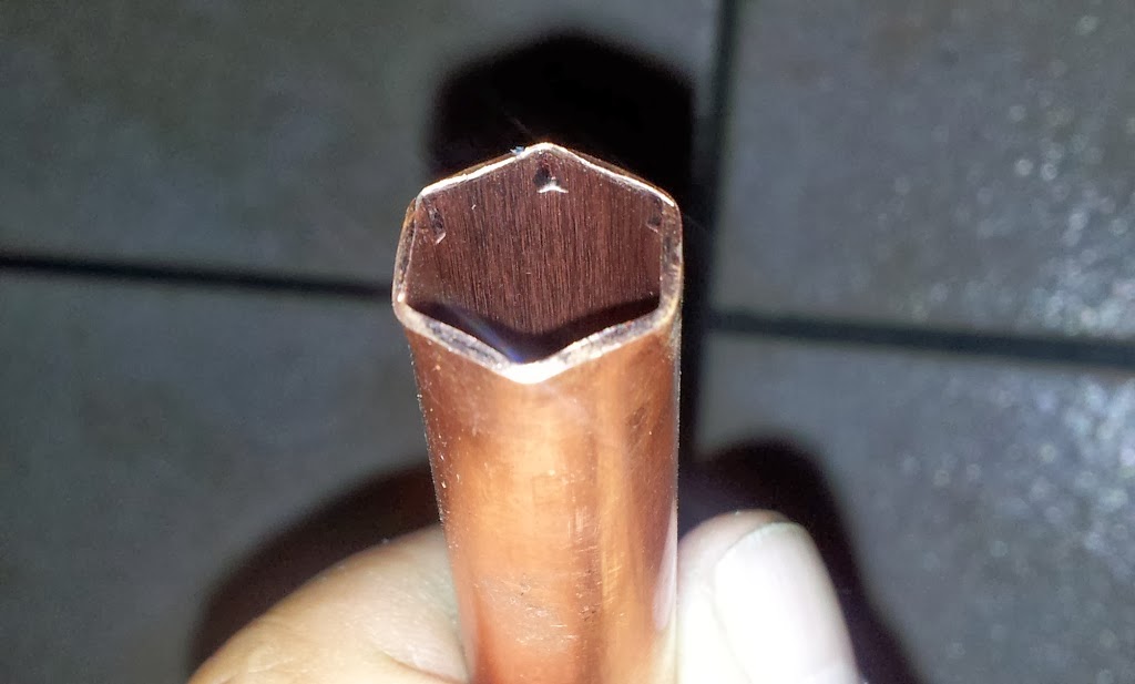
- Copper pipe 15mm, locally sourced, ZAR 56 (USD 5)
- Copper pipe 22mm, locally sourced, ZAR 59 (USD 5.50)
- Threaded rod M8, locally sourced, ZAR 15 (USD 1+)
- Timing belt and pulleys, locally sourced, ZAR 300 (USD 27) (including shipping for this and RAMPS)
- Heated bed and universal plate, locally sourced, ZAR 665 (USD 60)
- Bearings, locally sourced, 608z USD 1 each, F608Z USD 4.50 each, 6805z USD 5 each.
- Alpen SDS drill bit, locally sourced, ZAR 167 (USD 15)
- Smooth rod, locally sourced, ZAR 40 (USD 3-50)


Saturday 18 January 2014

J-head hotend

This morning I received an e-mail from the ebay store where I purchased the J-head hotend.  This was my very first Morgan purchase, shortly after Christmas.  They wanted to know whether I had received the hotend, and asked me to rate the purchase on ebay.

Of course, I HAD to go check the postbox before I responded (although I was there yesterday), and sure enough, the parcel was there. 

Back home this afternoon I wired the thermistor into the RAMPS connector, and connected the heater element to the appropriate connector.  I disabled the bed thermistor in the Marlin code and fired up Pronterface.

The J-head (sold as a MK V) is a clone from Hong Kong, judging by its 4 cooling fin slots as opposed to 5 (saw that on the internet somewhere) but it had a hollow set screw at the back holding the PTFE liner, and already wired up and Kapton taped together. The supplied wiring is just short of a meter.  No information on the thermistor that is mounted, so I selected thermistor '1' in the Marlin code.

Once Pronterface connected, I read the temperature, and it reported around 30 degrees C.  With the heat wave we have been experiencing lately, that was about right, so I selected 230 degrees C (ABS) from the drop-down and switched the heater on.  The LED on the RAMPS board lit up and I could feel the nozzle heating up immediately.

Pronterface can graph the temperature in real time and I saw it climb up to the target, once there, the LED switched off and started swithcing on occasionally.  Looks like bang-bang temperature control, as it flickers somewhat, but it tracked 230 degrees accurately.

With no way to confirm the temperature of the nozzle I pushed a piece of filament against the metal bottom of the J-head, and it melted as expected.  So far so good!  From the ammeter on my power supply it looks like approximately 3-4 Amps going into the heater element.


Friday 17 January 2014

Filament and thermistors

The filament I ordered arrived today, nicely sealed in plastic bags with a packet of silica gel dessicant inside the bag.  I don't know if that is standard practice but it is a nice touch as the ABS is prone to absorb moisture from the atmosphere.

I connected two thermistors to the RAMPS board, although totally out of calibration it reads temperature (bed and hot end) and reacts when I hold the sensor between my fingers. Pronterface now runs the print (previously it aborted due to no temperature reading). Obviously the program waits for the heaters to reach temperature (not connected) but at least it tries...

As soon as the stepper driver boards arrive I will start testing the motors.

Thursday 16 January 2014

Electronics components

I had to attend a meeting in Johannesburg today, so on the way back I drove past Mantech Electronics and PTFE Plastics.  At Mantech I picked up the Hall effect sensors for the endstops, as well as some thermistors.  The ones that I could get is too big to fit on the heated bed, but at least I can get testing, and at less than ZAR1-00 per thermistor it is not expensive.

PTFE Plastics supplies the tubing for the Bowden tube (from the extractor to the hot-end).  I purchased some 4mm OD, 2mm ID tube (I'm configuring the Morgan for 1.75mm filament).  Oh, and I ordered some ABS filament from Filament Factory in Roodepoort.  Best price I've seen, we'll see about quality.

I'm pretty much set now to start assembling the printer as soon as the printed parts arrive.  Those are being printed now at MorganHQ (at House4Hack in Centurion), the new base of operations for Quentin (designer of Morgan).

In the mail, still to be received, are the stepper drivers and hot-end.  In the mean time I am familiarising myself with the Morgan firmware.  Not that it is necessary to know how it works, only for myself.

Monday 13 January 2014

More stepper motors

The 1.8 degree stepper motors arrived today.  As I understand it, these are for use in the extruder and the z-axis. The 0.9 degree steppers are for the arms.  With no 1/32 microstepping drivers I will be sacrificing resolution, but the drivers are plug and play so I can always upgrade the resolution later.

Last night I also measured out all the holes on the top platform.  The dxf file shows arc-shaped slots on one side, and it seems that there were one or two machines (found some online photos) with fans blowing on the bed.  I have ignored these slots for the moment, I can always add a fan later if necessary.

Sunday 12 January 2014

Lazy weekend

Very little progress was made over the weekend, we rather went geocaching on Saturday.  Drove past House4Hack in Centurion - there is a geocache less than 100m away!  There is currently not much work that can be completed on my Morgan, as much of the parts are still underway.  This week I intend buying some endstops (Hall effect sensors), and a thermistor for the heated build plate.  That will enable more testing of the firmware.

My heated build plate currently has a plate glass top.  This might have to change, as I understand that the plastic (first layer) might not stick to glass as well as needed, and plate glass might have difficulty handling the temperature of the bed.  I have read of borosilicate glass tops (probably expensive), and I have read of sticking Kapton tape on the bed to build on.  If Kapton tape is needed, why not tape it directly to the heat bed (PCB)?  A lighter bed must be a good thing.

I have polished the smooth rods (using the electric drill and Brasso polish), as well as the 22mm copper tube (for aesthetic reasons :-) ).  I have also gone through the Marlin configuration code to see how the software distinguishes between 8825 (max 1/32 microstepping) and 4988 (max 1/16 microstepping) driver chips, as I have ordered Stepstick 1/16 (4988 based) drivers.

The microstepping is selected via two digital lines, and the (newer) 8825 stepper driver boards are configured to select 1/32 automatically when 1/16 (on the 4988) is selected in the software.  So, it is not something I need to worry about - the resolution is lower than it could be but does not need manual intervention.  Everything else is handled through the steps per degree constant. My Stepsticks are supplied with heat sinks and rated at 2A, so current handling should be good.

The power supply will be from my amateur radio - I have a 25A adjustable (switch mode) power supply that will be used for the moment.

Friday 10 January 2014

Playing with RAMPS

Today I started looking at the Arduino firmware.  As mentioned previously, I already own an Arduino Mega 2560 board and Arduino 1.0.5 is installed on my PC.  I fitted the RAMPS 1.4 board on the Mega, opened the Arduino "sketch", changed the hardware to RAMPS (1.3), option 33, compiled and loaded it onto the board.  No problems there.

I then fired up PrintRun (Pronterface), and connected to the electronics.  Again, no problems there but the expected failure to read any temperature inputs (none connected so far).  But it communicates, recognises the firmware, all looking good so far.

The chipboard base was also cut (freehand, this is temporary).

And just for fun, a photo:


Thursday 9 January 2014

And still they come...

After posting earlier, feeling satisfied with the stuff I received today, I had another phone call from a courier company - the first of the stepper motors (the 400 steps per revolution ones) were here! 

This evening I cut the PVC pipe to length (using the pipe cutter - the hacksaw and mitre box did not look square to my eye).  I also cut a cork sheet (bought as gasket material for my old Land Rover) to size to insulate the bottom of the heated bed from the universal build plate, and screwed that bit together (finger tight).

And I've started measuring out the build platform.  At the moment it is a piece of MDF (chipboard) I have in the garage, but a friend who is into woodworking promised to make me a beautiful platform - with routed edges and all.  But that will come later.

Pretty soon I'm going to start itching for the printed parts - but I know there is a delay.  The rest of the stuff is happening quicker than I thought.  As far as I can see, I need very little further parts - the end-stops, the PTFE tubing, the idler spring, Kapton tape, and filament.  The rest is here or on its way...

Fast and Furious

Today was a good day.  I managed to find the 8mm Alpen SDS masonry drill bit in the long (450mm) length at our local Timber City branch.  And even cheaper than the shorter ones I saw in other hardware stores.

Two parcels were waiting at the post office, and I also received the couriered Micro Robotics package (RAMPS board, timing belt and pulleys).  The two parcels at the post office contained the LM8UU linear bearings in one, and the OpenHardware universal plate and heated bed in the other.

While out, I also ran into our steel merchant for smooth rods, they referred me to a manufacturer of stainless steel products across the road, and the proprietor cut me two 440mm lengths while I waited.  Around the corner was a glass place where I had a 200mm x 200mm piece of 3mm plate glass cut.

Finally, last night I ordered a pack of 5 Pololu stepper driver boards off ebay - free shipping so even with the VAT and customs fee we have to pay at the post office it is still an excellent deal.

And just for readers who are not familiar with what I'm trying to achieve, here is a picture (shamelessly lifted off the net):


Wednesday 8 January 2014

Progress

I received my ordered bearings today - all three flavours (608Z, F608Z and 6805Z), and the price was better than quoted verbally over the phone.  I bought too many, I think, the various BOMs and descriptions do not all agree.  I have enough, though.

With the printed parts still on back-order, I did a mock assembly of the drive shaft.  It needs the rod-mounted drive wheel in order to be tightened, but I'm excited so I am dry-running the assembly to make sure I have everything and understand the instructions.

The courier company also called to confirm that my package (RAMPS, timing belt and pulleys) will be delivered today.

A photo of the semi-assembled drive shaft alongside the PVC pipe ("the right stuff"), still uncut.


Now I need to figure out how to squarely and accurately cut the PVC pipe to length.  My pipe cutter (used for the copper pipe) is only up to 30mm diameter.  A hacksaw and mitre box seems a bit inaccurate.  I will probably just use that and finish the ends with sand paper, otherwise my tools is going to end up costing me more than the Morgan.

Monday 6 January 2014

Frustration

Sourcing some of the vitamins for my Morgan build is turning out to be frustrating, to say the least.  I had to go into the office (Bryanston) today (first day of work), and decided to see if I could buy the PVC pipe and SDS drill bit while there.

The drill bit is available in 310 mm overall length (250 mm thread), but not the longer 450/400 length.  I have found 10mm bits in that length, and many OTHER brands in long lengths, but not the Alpen bit.  No success yet (and I visited no less than FOUR Builder's Warehouse branches and THREE Micas, and various other hardware stores).

I can order a bit online, but the price seems to be around R1000 (as opposed to less than R200 in the brick-and-mortar stores).  Not an option.

On the PVC pipe front, the best I could do was 32mm OD flexible pipe (as used in garden irrigation systems), which is not what I want.  Eventually I ended up driving past Incledon in Germiston on the way home and buying 6m of the right stuff (32mm OD class 16 (2.4mm wall thickness) PVC pipe).  Enough for THREE Morgans, for under R70.

Positive news was a phone call from Micro Robotics looking for a physical address to courier parts (RAMPS, and timing belt/pulleys) to, and the OpenHardware order (plate and heated bed) has also shipped via the post office!


Sunday 5 January 2014

First images

In my previous post I failed to mention the LM8UU linear bearings I also ordered off ebay.  Just for completeness sake...

The promised photos - the copper pipes cut to length, and two pictures showing the fitting of the M8 nut at the end of the 15mm pipe:


Saturday 4 January 2014

Basics

Even though I can build circuit boards (from "first principles", i.e. CAD drawings), I have decided to try to get up and running as quickly as possible, and to order most of the stuff ready-built.  I might later see if it is worthwhile compiling kits or building up boards and offering them for sale, as my previous career as design engineer have left me with all the contacts for cost-effective manufacturing.  But for the moment, the mission is to get a working printer.

Hardware:

I have decided on the following for the Morgan (see Quentin Harley's blog http://www.reprapmorgan.com).  I have an Arduino Mega board with the software design tools from a previous project, so the interface to the printer is in the form of a RAMPS 1.4 board.  Stepper drivers still needs to be decided on.

The print head I ordered from e-bay (J-head), and also the stepper motors (I bought some extra).  Printed parts from Quentin himself, universal build plate and heated bed from Openhardware, and the RAMPS board, stepper pulleys and timing belt from Micro Robotics.

All of these are still in the process of delivery, so today I visited the hardware shops and started purchasing "vitamins", or the hardware necessary to complete the build.  Builders Warehouse is my friend..., except that I could not source the (rather long) Alpen SDS drill bit.  Witbank hardware stores stock bits up to 250mm in length, and I need 400mm.  Luckily I know the owner of Middelburg Mica so maybe he can help (order one if necessary).

The bearings will also be ordered on Monday.  One thing about Witbank, with all the mining activity in the area, engineering supply shops are in good supply.

Software:

I have downloaded the Morgan firmware (obviously), as well as OpenSCAD, Slic3r, and Pronterface (PrintRun).  This seems to be all I need to get going (OpenSCAD only if I want to create parts from scratch).  I have previously played with SketchUp (when it was still with Google) and Blender (in my Linux days), and I like the text-based language for OpenSCAD (it reminds me of Matlab at varsity many many years ago).

Photos of my first days progress will follow...

An Unexpected Journey

So, I have embarked on the journey of building myself a RepRap 3D printer.  The decision has been a long time coming, without me even knowing it.  I have always been intrigued by doing things by and for myself, to the point of starting to build a Gingery lathe several years ago. Unfortunately life got in the way of that adventure, and I ended up with a small charcoal foundry, a lot of scrap aluminium and a few cast ingots, but no lathe parts!

3D printing has been "inaccessible", at least in my mind, and discovering Quentin Harley's RepRap Morgan project over the December holidays was just what I needed.  Here was someone who built a 3D printer in Centurion (my old home town)!  I promptly started immersing myself in everything RepRap, to at least understand what all these websites are talking about.  I found that many RepRappers tend to assume that you are familiar with the technologies, terms and history of RepRap, and decided to create this blog to help others like myself, who are keen to learn.

As an electronics engineer by training and involved in embedded software development (less of that lately), I consider myself well equipped to successfully get a Morgan up and running.  Maybe this blog of my journey will help another aspirant RepRapper along the exciting journey.